A Brief z80 Assembly Tutorial
Chapter 12
I've never played with the AY-3-8910 audio chip before, so I need to do some research on it before we can dig in. While doing the research I couldn't find a definitive guide to programming the chip, but I'll present what I've found here. Thereby let's start with a section I decided to call..
All You Ever Wanted to Know About AY-3-8910 Programming but Didn't Know To Ask
From the speccy point of view, the chip is hooked into two ports: 0xFFFD to select register and 0xBFFD to write to said register. There AY chip itself has 16 registers, with 15 available on the spectrum, and we only care about 14 of them to control, practically, 10 different values.
As a side note, there's a peripheral for the spectrum called TurboSound which simply has two AY chips, and the Spectrum Next features TurboSound Next which has three. According to wikipedia, Konami's Gyruss used five.
AY Registers
The registers are as follows:
- 0x00: Channel 1 fine pitch
- 0x01: Channel 1 coarse pitch (4 bits)
- 0x02: Channel 2 fine pitch
- 0x03: Channel 2 coarse pitch (4 bits)
- 0x04: Channel 3 fine pitch
- 0x05: Channel 3 coarse pitch (4 bits)
- 0x06: Noise pitch (5 bits)
- 0x07: Mixer
- 0x08: Channel 1 volume (4 bits) / Envelope enable (1 bit)
- 0x09: Channel 2 volume (4 bits) / Envelope enable (1 bit)
- 0x0A: Channel 3 volume (4 bits) / Envelope enable (1 bit)
- 0x0B: Envelope fine duration
- 0x0C: Envelope coarse duration
- 0x0D: Envelope shape (4 bits)
- 0x0E: I/O port 1
- 0x0F: I/O port 2 (not in spectrum)
When selecting a register, it's important to not have any garbage in the unused bits, as the AY chip may use those for chip identification. Most AY chips have the ID of 0, but there are some out there with a different ID, with the idea that you can have several AY chips listening to the same bus and only react to the messages meant for it. This means that if you by mistake write to the ID field, the AY chip will consider them to be meant for someone else.
The AY silicon itself has two I/O ports for communication, but only one is wired in this variant, to have a chip in a smaller package to save PCB costs. There is a full scale variant with both ports, as well as a variant with neither, but since the smaller variant only saves a couple of pins, it wasn't as popular. The I/O port is, as I understand it, used for MIDI, and we won't care about it.
There are three channels of square wave generators, with 12 bit pitch control and 4 bits for volume (so yes, there's just 16 discrete volume settings); one noise generator with 5 bits for pitch, and one envelope generator with 16 (well, 8-ish) different shapes and 16 bits of period.
The "pitch" is a misnomer as it's actually delay period; the smaller the "pitch", the higher the sound. The pitch can be calculated via (chipfreq/16)/frequency. Chip frequency varies from one machine to the next; Amstrad CPC used 1000000, Atari ST went with 2000000, and the one on spectrum uses a nice round 1774400. So for a 220Hz tone, we need pitch of (1774400 / 16) / 220 = 504, and for 440Hz the pitch goes down to 247.
A channel's volume can be set directly, or channel can be set to use the envelope for volume control.
Furthermore there's configuration flags (mixer) saying which channels should be active and whether noise is mixed in. Six bits of mixer state which channels tone is on and which channels noise is on, and the remaining two bits are related to the I/O port operation.
Writing to the envelope shape register also resets the envelope.
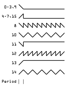
And here's what the envelopes look like. I presume the designers wanted to achieve 4 envelope types (or so) and the rest (including the various duplicates) are a side effect of the implementation.
So What Does It Look Like
Let's enable feature by feature and look at the waveforms.
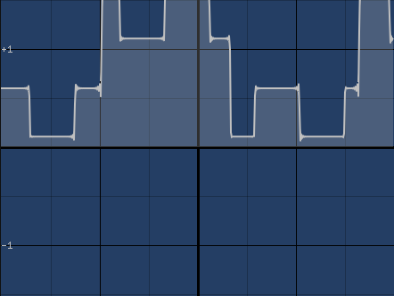
Enabling channel 1, pumping the max gives us something like this:
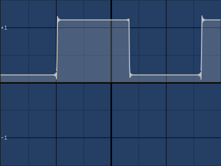
Channel 1 on
Yes, it's a square wave. We are amazed. The reason why we are slightly offset from 0 is that channel 3 had volume turned up. Even though the channel was not enabled, it contributes DC offset. This (probably?) won't matter much when programming the chip, but it does affect our measurements here.
Let's disable channel 1 and enable noise
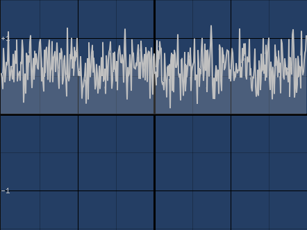
Noise 1 on
Well, that's noise. Not really sure what I was expecting.
Channel 1 on, noise 1 on
Enabling both the channel and noise gives us ring modulation of noise and the square wave.
Channel 1 on, channel 2 on
Here I enabled channel 2 with a shorter period (i.e, higher pitch) and lower volume. The result is slightly superwave-ish.
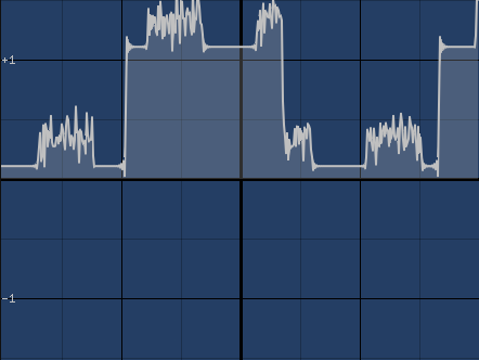
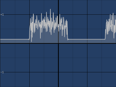
Channel 1 on, channel 2 on, noise 2 on
Enabling noise on channel 2 does what we can expect a this point. We could do the same things with the third channel, but how things work on this level is pretty clear at this point. Let's look at envelopes.
Let's start with envelope off and pitch relatively high (by which we mean that the pitch value given to the chip is small, so the audio pitch is high).
Channel 3 on
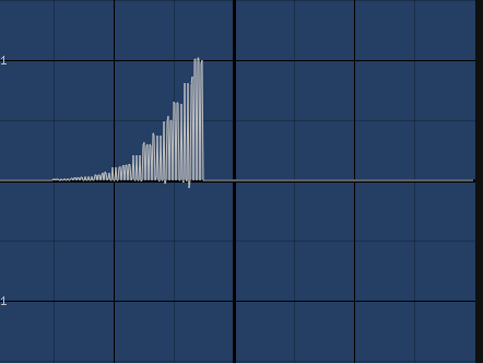
Then we enable the envelope control for the channel, set envelope shape to 0 and trigger the envelope.
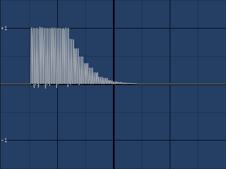
Channel 3 on, envelope 0
We needed to zoom out a bit to see what the envelope does.
As expected, the volume slopes down and then stays at zero, as that's what the envelope was. The volume will stay at maximum as long as we keep resetting the envelope, and then slopes down. Let's try a couple more.
Channel 3 on, envelope 4
The volume rises, then drops to zero and stays there.
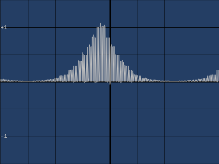
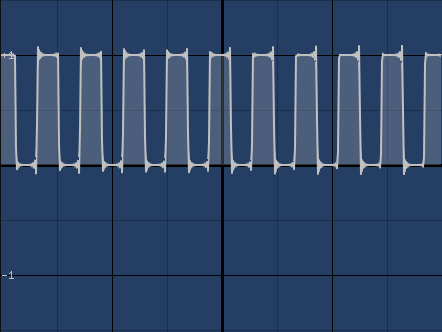
Channel 3 on, envelope 10
Volume rises and falls on subsequent periods. This is what the AY's vision of a triangle wave looks like.
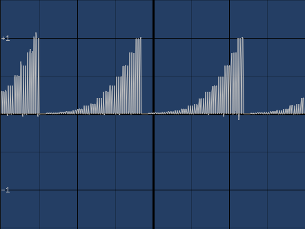
Channel 3 on, envelope 12
And this is what the saw wave (or one of them, anyway) looks like. Let's try this again with the tone off and noise on.
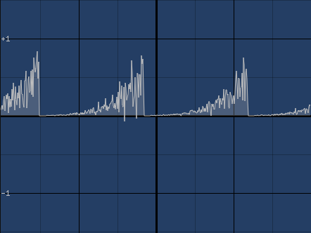
Noise 3 on, envelope 12
That looks pretty nice, actually.
Anyway, you must be really tired of all these graphs by now, but I hope they've given some kind of idea of the capabilities (and limitations) of the device.
Limitations of note:
- Volume is either set, or uses envelope; not both.
- Noise uses channel volume. Would be nice to have separate volume for channel's tone and noise, but that's not happening. Unless you use two channels, I guess, but there's no guarantees they will play in sync.
- Only one noise pitch. If there were several, could do nice noise slides in sound effects.
- Only one envelope. Same problem here. Having just the one limits its uses - either it's on a global setting or tied to a single channel, basically.
The Grand Plan
Talking of limitations.. since there's only one noise pitch and only one envelope, the applicability of these two features is rather limited. What we're after is a pretty general sound effects system, so we'll limit ourselves to a single pitch of noise, no envelope (or a repeating envelope set to a single setting), so we can have three identical sound effect channels we can populate in a round-robin way.
Musically there would be more options. Dedicate one channel for drums and alter the noise pitch as needed for hats and cymbals. Careful timing would make it possible to do saw or square wave on a single channel. Even more careful timing, impossible on a speccy (but possible, and done on Atari ST and Spectrum Next) you could even have pulse width modulation.
Instead of using the envelope on the chip, we'll do it ourselves, updating the AY registers on every frame. That means our audio control will only change every 20ms, but that's how vast majority of AY music works in any case.
In addition to a volume envelope we can do pitch changes, which is (largely) what sound effects are all about.
Enough theory, this is going to be long enough chapter as it is.
Sound Data
First we need to define what our sound effect data looks like. We want volume and volume ramps, tone and tone ramps, we need to be able to pick tone, noise or both, and finally we want the sounds to end eventually.
        STRUCT SFX
pitch:  DW  ; Initial pitch
pitchi: DW  ; Pitch increment
volume: DW  ; Initial volume (*256)
volumei:DW  ; Volume increment
flags:  DB  ; Tone on, noise on, envelope on(?)
length: DB  ; Length in frames (50hz)
        ENDS
We're still not sure what to do with the envelopes, but if we want to enable them, there's plenty of space in the flags.
snd_test:
        SFX {
        1024,
        128,
        15 * 256,
        -170,
        1,
        21
        }
Here's what a sound will look like. Remember, the lower the "pitch" value, the higher the tone. Volume we set to the max (15), fading out. We want tone to be on and noise off, and the sound shall play for 21 frames (21*(1/50)=0.42 seconds). The pitch will be 2688 and volume will be near 1*256 when we stop.
ch1:    SFX{}
ch2:    SFX{}
ch3:    SFX{}
The Play Function
Next we need the data for our sound channels, which we'll just initialize as three copes of the SFX structure.
nextch: db 0

; Function playsound. hl = sound effect to play.
playsound:
    ld a, (nextch)
    cp 0
    jr z, play_ch1
    cp 1
    jr z, play_ch2
    ld a, 0
    ld (nextch), a
    ld de, ch3
    jr play
play_ch1:
    inc a
    ld (nextch), a
    ld de, ch1
    jr play
play_ch2:
    inc a
    ld (nextch), a
    ld de, ch2
play:
    ld bc, 10
    ldir
    ret
To play a sound, we simply memcpy the sound we want over a channel. The playsound function goes through the channels in a round robin way using the nextch variable, meaning that we always overwrite the oldest sound. This is probably the easiest way to pick a channel; we could look for the one with the smallest volume, or the one that has the least frames left to play, but this will do.
We also could have given some kind of index to sound effect as a parameter - as we probably would have, on some higher level language - but we have no reason not to just give the address of data to copy.
To test things out, let's add test code.
        ld hl, snd_test
        call playsound
Those two lines can go anywhere, but I put them right before the input select loop. Compiling and running reveals that nothing happened, which is a good thing, considering we haven't written to any output ports yet.
With everything else in place, it's time to tackle the player, which goes into our ISR.
The Actual Sound Player
Step one is to remove the frame counter, which we aren't using for anything, which will leave an empty ISR which only enables interrupts and returns. Then we fill it out.
isr:                    ; This will be called ~50Hz
        ex af, af'
        exx
To start off, we need to deal with the fact that the ISR may occur at any point in time, so we need to preserve registers. Typically this means pushing and popping all the registers we alter in the ISR, but since we're not using the alternate register bank anywhere in our program (spoiler: this isn't true), we might as well use it here. The EX AF, AF' command, apart from being the bane of all syntax highlighters, swaps the A and F registers with the alternate versions. EXX does the same for BC, DE and HL. The reason these are two separate operations, as I can tell, is that this way there's at least some way to transfer data between the two sets, even if that's a single 8 bit value.
        MACRO PERCHANNEL pitch, pitchi, finepitchreg, coarsepitchreg, volume, volumei, volumereg
            ld hl, (pitch)
            ld bc, (pitchi)
            add hl, bc
            ld (pitch),hl

            ld bc, 0xFFFD
            ld a, finepitchreg
            out (c), a
            ld bc, 0xBFFD
            out (c), l
            ld bc, 0xFFFD
            ld a, coarsepitchreg
            out (c), a
            ld bc, 0xBFFD
            out (c), h
We have three channels and a lot to do for each, so it's simplest to just do a macro about it. First off we take the channel's pitch and apply pitch shift to it, storing the altered value back. Then we write the coarse and fine bytes to the appropriate ports. The coarse part uses 4 bits out of 8, but since there's nothing on the upper part of the register, we won't bother cleaning them out. (This may bite us if some future chip defines something here, but let's hope not).
Even though the syntax for OUT (C) only mentions the register C, it's actually using the whole 16 bit BC. There's also a OUT (N) variant which takes constant as the port value, but that unfortunately only works for 8 bit port addresses, so we have to go the BC way.
            ld hl, (volume)
            ld bc, (volumei)
            add hl, bc
            ld (volume), hl
            ld a, h
            and 15
            ; todo: if we want to enable envelope, here's the place

            ld h, volumereg
            ld bc, 0xFFFD
            out (c), h
            ld bc, 0xBFFD
            out (c), a
        ENDM
Same process goes with the volume setting. Here we mask the output before writing, because the bit right after the 4 volume bits controls whether the chip should use the volume or envelope for the volume setting.
        PERCHANNEL ch1.pitch, ch1.pitchi, 0, 1, ch1.volume, ch1.volumei, 8
        PERCHANNEL ch2.pitch, ch2.pitchi, 2, 3, ch2.volume, ch2.volumei, 9
        PERCHANNEL ch3.pitch, ch3.pitchi, 4, 5, ch3.volume, ch3.volumei, 10
Then we apply the macro for our three channels.
        ; Handle mixer. Bottom 3 bits for tone enable, next 3 bits for noise enable.
        ld de, (ch1.flags)
        ld a, 0
        bit 0, e
        jr nz, ch1_toneskip
        set 0, a
ch1_toneskip:
        bit 1, e
        jr nz, ch1_noiseskip
        set 3, a
ch1_noiseskip:
More repetitive code follows. We need to figure out what to write to the mixer register, so for each channel we check if the channel wants tone or noise and collect the bits to the A register.
        ld bc, 0xFFFD
        ld d, 7
        out (c), d
        ld bc, 0xBFFD
        out (c), a
And once all three channels have been investigated, we write the mixer register.
        ld a, (ch1.length)
        dec a
        jr nz, ch1_endskip:
        ld (ch1.flags), a
        ld hl, 0
        ld (ch1.volume), hl
        ld (ch1.volumei), hl
ch1_endskip:
        ld (ch1.length), a
Since we want the sounds to end eventually, we decrement the length field, and if we hit zero, we set the flags to zero (disabling it in mixer) as well as set the volume and volume increment to zero. On the next cycle the length will underflow going to 255, and unless some new sound is played on this channel we'll mute it again in about 5 seconds.
        exx
        ex af, af'
        ei
        reti            ; Return from interrupt
And in the end, we swap back to the other register set, and that's it - we now can have sound effects.
As the EXX and EX instructions don't use stack their order doesn't really matter, but it's nice to keep these in reverse order to undo what we did earlier.
Since we're comfortably running at 50Hz, we technically wouldn't need to do the audio processing in the ISR. In fact, doing it in the ISR makes things a bit worse for us, as it's the first thing done in a frame, where we'd rather be putting pixels on screen before the screen draw starts. But doing it this way means that if the frame rate should ever dip to the second frame, the sounds, at least, won't sound wonky.
Small Fixes
Compiling and running makes the sound, but the program hangs. This is because we actually are using the alternate register set - not in code we wrote, but in the image decompressor. Decompressing the image takes more than a single frame, so we mess up the decompressor. The fix is pretty simple:
        di
        call dzx0_standard
        ei
By disabling interrupts while decompressing, we don't have this problem anymore.
To test the thing in action, let's define a sound effect for player moving.
snd_walk:
        SFX {
        0,
        0,
        7 * 256,
        -70,
        2,
        5
        }
This is a quite quiet, short white noise. We don't write to the noise pitch register, so the noise pitch will be whatever it is when our program starts - we probably should set it to some known value.
To make the playsound callable from anywhere, we need to preserve the registers it uses:
    push af
    push de
    push bc
...
    pop bc
    pop de
    pop af
We really should have done that in the first place. The function also messes up HL, but since that's the input parameter, it doesn't matter.
We'll plop the function call in the appropriate place:
moveok:
        ld (playerpos), hl

        ld hl, snd_walk
        call playsound
And now there's sound whenever the player moves. What's left to do here is design a bunch of sound effects and pepper them all around the moveplayer and physics functions, but I think we're done for the chapter.
This chapter's version of the source is available here.
Size-wise we're at 6149 bytes, up 415 bytes. The size will grow by 10 bytes per sound effect data and 6 bytes per sound effect call (assuming we don't need to preserve HL, in which case add 2 bytes per call), so adding sounds from now on is relatively cheap, size-wise. Let's say we add 10 sound effects: cost will be 160 bytes. Not bad.
Any comments etc. can be emailed to me.