Speccy, Vol 13: Everything You Need to Know About 48k ZX Spectrum
November 28th, 2024
I've had several situations where it would be beneficial to point someone at a single page that had a short description of the 48k ZX Spectrum, so here we go!
Internals


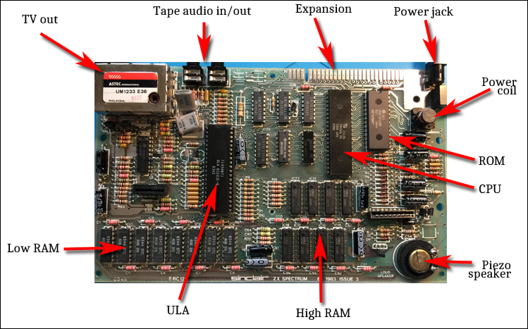
(credits: board photo stolen from here, chip identification from here)
The 48k ZX Spectrum is an astonishingly simple machine by modern (and, I guess, historical) standards. Looking at the circuit board, there's a handful of chips plus some supporting circuitry. There's various issues (versions) of the board around, but the main bits remain the same.
The output was TV signal, because back in the day you'd plug your home computer to the family TV. For storage, the computer used C-casette tapes, and you'd need to bring your own, plug the "mic" and "ear" cables to the computer for loading and saving of programs to tape.
The expansions were handled via simply exposing a lot of signals on the edge of the circuit board.
Power input was 9V barrel jack which from modern standards point of view has barrel/pin polarity reversed, which is an easy way to destroy vintage hardware.
The power was transformed down to several voltage levels internally, and there's a coil which probably (likely thanks to the age of these parts) makes a lot of scary noise. I put some super glue in mine to kill the noise a bit. Whether that was a good idea or not, I have no idea, but it seems to work. Someone suggested using honey.
CPU is a Zilog Z80 clone, or in some rare cases an actual Zilog Z80.
There's 16k of "low" RAM which the ULA shares with the CPU, 32k of "high" RAM which the CPU has all for itself and 16k of ROM.
For audio output there's a piezo speaker.
Finally, there's an ULA. ULA can be seen as a forefather of FPGAs, except it's not field programmable. Cheaper than making actual ASICs, but more limited. The ULA is (largely) what makes speccy a speccy. You can't take the ROM from other z80 based machines, drop them into a speccy and turn it into, say, an aquarius.
Keyboard


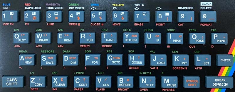
(keyboard photo stolen from here)
Anyone trying to use a speccy for the first time will notice the very, very annotated keyboard. The device's operating system is a BASIC interpreter, and the commands are largely single button press deals. The keyboard was rubber, so you wouldn't want to type a lot with it - maybe this was the reason why they went with this design. So if you want to load a program, you'd press J for Load, and (if I recall correctly) symbol shift-P twice for "".
Internally, the code is also not stored as plaintext, but instead as tokens. So that "load" is actually stored as a single 0xEF byte. This saves both on processing and memory.
Later (128k+) models had a (somewhat) better keyboard and you could type BASIC character by character, but it would still be stored as tokens.
Memory


Looking at the speccy memory map, the bottom 16k is ROM, which we can't do anything about, followed by 6144 bytes of display bitmap plus 768 bytes of color, leaving 65536 - (16384 + 6144 + 768) = 42240 bytes of RAM.
The bottom 16k of RAM is "contended", meaning its shared with the CPU and the ULA. If the ULA is busy, the CPU will wait. In Amiga terms, the bottom 16k is "chip" ram, and the top 32k is "fast" ram. The display buffers live in the bottom 16k of RAM, leaving 9472 bytes of contended RAM for software use. You'll probably want your code to live in the upper 32k so it runs as fast as possible.
If the 32k sounds like a very small amount of memory for everything, consider this: There was a 16k version of the ZX Spectrum, which simply didn't have the chips for the top 32k of memory, and some very, very successful games were made for that setup - using that mere 9472 bytes of available RAM! (Just the plain text of this single web page, which didn't take me all that long to write, is way longer than 9472 bytes). On the positive side, z80 code is pretty compact - it's assets (graphics, text, etc) that require a lot of memory.
If you want to use BASIC or the default ROM interrupt handler, there's also a bunch of system variables that reside after the display data, plus custom character bitmaps that are at the very end of the memory space. If you are planning on having your program take over the machine and not use the ROM routines, you don't need to care about these.
The z80 CPU will only ever see 64k of memory. In the 48k speccy's case, the bottom 16k is ROM, next 16k is contended RAM, and the rest is uncontended RAM. So when Spain's tax laws caused 128k machines to enter the market, how did that work? By banking. Or in other words, certain memory regions were a "window" to the RAM, and you could tell the hardware to change what the window showed. This, however, is outside the scope of this document.
Display
Speccy's graphics mode is rather funky in several ways. First, you have 256x192 pixel bitmap, meaning each pixel is either black or white. On top of this bitmap there's a 32x24 color map, where each cell covers 8x8 pixels of the bitmap, changing the "black" and "white" to something else. The speccy terms for these are "paper" and "ink".
The 8 bits per 8x8 cell go like this: FBPPPIII
There's three bits for ink, three bits for paper, one for bright, and one for flash. Three bits means there's 8 different colors (which are conveniently printed on the keyboard): black, blue, red, magenta, green, cyan, yellow and white. The paper and ink share the bright bit, meaning you have total of 16 (well, 15) different colors you can output. Black is always black, though. This system means you can't have both dark blue and bright blue in the same 8x8 cell. It's not a great system.
The flash bit means the paper and ink of that cell flips every 16 frames (3.125 Hz).
Trying to do pixel-perfect colored sprites leads to the color clash speccy is known for.
But it gets better! The memory layout for the bitmap isn't linear. The color stuff is, but the bitmap isn't. As I understand it, reading the memory in a linear fashion would be too slow for video generation, so having it swizzled this way lets the ULA fetch stuff from several memory chips at once.
From software writer's point of view it's a bit painful, though. Address for the video memory goes like this:
C0 C1 C2 Y7 Y6 Y2 Y1 Y0 Y5 Y4 Y3 X4 X3 X2 X1 X0
The C bits are always 0 1 0. Bottom 5 bits are linear X coordinate ones (5 bits giving us range of 32, and 32 * 8 gives the horizontal resolution of 256). So as long as you can find the scanline you're drawing to, horizontal movement is simple. Math for grid-aligned 8 character tall things is also very simple due to Y0, Y1 and Y2 being linear (and at the bottom of the higher byte of the address). Outside that, things get a bit hairy.
I've found that the easiest way to deal with this is to just sacrifice 384 bytes for a scanline look-up table, but there are other solutions.
Interrupt
The device has a single interrupt, which occurs at the start of the display refresh. You can wait for the interrupt by simply using the HALT instruction. By default, the interrupt calls a ROM routine, which, among other things, scans the keyboard and does some stuff with the system variables. Unless you're making a program for the 16k spectrum, you will likely want to replace the interrupt routine with something else.
The z80 has three interrupt modes. First one jumps to the ROM area, second (as far as I recall) reads an operation from an I/O port, and the third one reads a 8 bit offset to an interrupt table from the I/O port. Since we have no control over what is read from the I/O port, the second mode is out, and the third one is tricky, but usable.
Basically you need to set up a 257 byte table at an 8-bit even address where each byte of the table has the same value (so when a 16 bit value is read, the result is the same regardless of whether the offset read is even or odd). In other words, if we have the table starting off 0xfe00 with 257 0xfd bytes, and the interrupt registers set to use these thingies and the proper mode, whenever the interrupt occurs, control will go to address 0xfdfd which can then be a jump to your actual interrupt routine. Or a RETI if you don't want to do anything special. (Or RET, since the speccy has no peripherals that depend on the RETI variant).
The hardware also has NMI interrupt, which for multiple reasons is unusable on the 48k speccy.
Input
Speccy didn't come with a standard joystick interface, which is why most speccy games start off with a menu where you can choose which joystick standard your controller uses or if you want to play with the keyboard. To make things worse, various incompatible joystick standards overlap, so you can't auto-detect anything.
The keyboard is read by reading the I/O port 0xfe. Or more specifically 0xfefe, 0xfdfe, 0xfbfe, 0xf7fe, 0xeffe, 0xdffe, 0xbffe and 0x7ffe. But the 0xfe will come back to haunt us. Each of those ports refers to 5 keys on the keyboard, with 0 meaning a key is pressed and 1 meaning key isn't pressed. Bit 6 is signal from the EAR plug. As you'd expect.
Kempston joystick, which probably has the widest support in speccy software, is read from port 31, and is inverse from the keyboard, meaning 1 is key pressed and 0 is key isn't pressed.
Audio
In input we were reading from 0xfe. So what happens if we write to it?
The bits go 000EMBBB.
The B bits set the border color. This is particularly useful when showing progress (such as when tape is being loaded), or to time things. Have your routine synchronized with the interrupt, change border color when the thing you're interested in starts and ends, and you'll see how much time of the frame it took. Border color only gets three bits; the border can't be bright.
The M bit is for saving to tape. And finally, the E bit is hooked to the piezo speaker. To make a sound, toggle the bit on and off at your preferred frequency. And how do you do that? Usually through busy loops. Toggle, loop, toggle, loop. Won't be able to do much work while sound is playing, which explains why speccy games tend to have music in intro screens and the gameplay has very short chirps.
That's All Folks
And that's basically the whole machine. It's possible to dive deeper in all aspects. L Break Into Program has excellent articles on a lot of these things. My z80 programming tutorial on this site covers a lot of these things in practice (and you'll end up with a game to boot).
The 128k spectrums built on these foundations by adding memory mapping and AY sound chips; various clones added features, and the ZX Spectrum Next ties a lot of these things together, and expands things further.
Comments, etc, welcome.