What is Atanua?
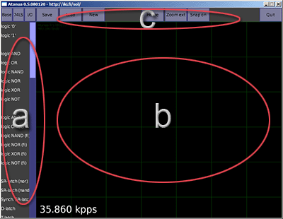
The Atanua UI
Atanua![]() is a real-time logic simulator, designed to help in learning of basic boolean logic and electronics.
It uses OpenGL hardware-accelerated rendering and a custom UI designed for a fast workflow and a very low learning curve, letting the students concentrate on learning the subject instead of spending time learning the tool.
is a real-time logic simulator, designed to help in learning of basic boolean logic and electronics.
It uses OpenGL hardware-accelerated rendering and a custom UI designed for a fast workflow and a very low learning curve, letting the students concentrate on learning the subject instead of spending time learning the tool.
See the interactive flash demo!
See the Atanua Google+ page!
Discuss on Google+ Atanua User community!
The Atanua UI consists of basically three parts:
- the component list
- the work area
- buttons for some useful functions, like saving and loading
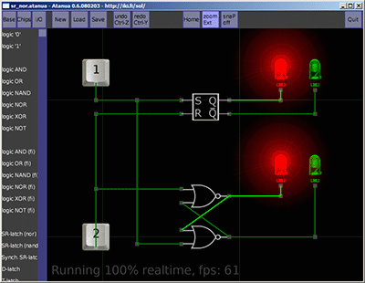
Simple example - SR latch, two implementations
As a simple example, the image on the left shows the implementation of a SR-latch using two NOR gates, as well as a SR-latch logic block, and both are connected to a couple of input buttons (bound to keyboard keys 1 and 2) and output LEDs.
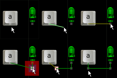
Editing wires
This example can be replicated by simply dragging the needed components from the component list to the work area, and connecting the parts with lines. The simulation is already running at a steady 1kHz.
To split a wire (for those 90' angles), simply drag at the middle of a wire. If you make mistakes, Control-Z is the undo.
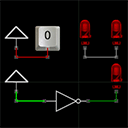
The 4 signal states
You can scroll around the work area by simply dragging it. You can also zoom in and out using the mouse wheel, or with keypad '+' and '-'. Escape and right mouse button cancel actions.
Wire colors show the state of the connection.
- Gray wire means there's no signal input.
- Red means there's more than one signal input, or something else is wrong.
- Bright green is signal high.
- Dark green is signal low.
Another example
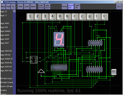
This is a slightly more complicated example - 7-segment driver, counter chip, and test buttons for everything - nothing really special, but enough to show that Atanua can also be used for nontrivial circuits.
Helpful tooltips
Site design © 2013 Jari Komppa (Mastodon)