A Brief z80 Assembly Tutorial
Chapter 2
Last time we left off with toolkit and minimal framework for what we're planning to do. The next step is to decide what kind of game we're going to make, and I decided to go with a boulder-dash-ish game. Since I'm going to reduce the scope by not having scrolling or many of the other niceties of the actual boulder dash, I'll be calling this game "stonewalk".
I decided that the map shall be 8x8 tiles that are 16x16 pixels each. That makes it easy to deal with color clash, since the colors are nicely within their 8x8 pixel grid. The whole map will take 128x128 pixels of our 256x192 screen, which is fine to start with; if we feel like it, it will be trivial to expand that to 256x192 (16x12 tiles) later on, but let's start with this.
Doodling Tiles
First order of business is to draw some tiles, so I did:

Okay, I'm no artist. And this is speccy we're talking about. Wait until it gets color!
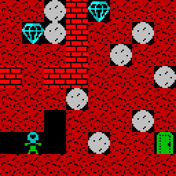
Well, it still looks like speccy, and I'm still no artist.
The tiles are arranged in my image in a top down manner so they'll be easy to index in code. I then turned these tiles to a bitmap using my "png2bin" tool from my speccy github. Despite its name it'll load most image formats thanks to stb_image.h.
I decided that I'd add color directly in the source file. Next, we'll need to get the tiles on the screen, which is what this chapter is actually about.
Drawing Tiles On Screen
If you download the chapter 2 zip you'll find "tiles.dat" and the changed "test.s" in it. (To compile, you'll need the chapter 1 files too). The first changed bit is the main loop, which now looks like this:
mainloop:
        ld hl, map+63
        ld bc, 0x0808
maploop:
        push hl
        push bc
        ld a, (hl)
        ld l, a
        ld h, 0
        call drawtile
        pop bc
        pop hl
        dec hl
        dec b
        jr nz, maploop
        ld b, 8
        dec c
        jr nz, maploop
        jp mainloop
First we set HL to point at the end of our map data (8x8 tiles means 64 bytes for the map), and BC to have 8 in B and 8 in C.
Within the map drawing loop we first PUSH HL and BC because they'll be destroyed by our tile drawing function; to further prepare the function call we read the tile number from the map and store it in HL. Then, we call drawtile to do the actual tile drawing.
After drawtile has done its thing and wrecked all our registers, we POP BC and HL back from stack (note the reverse order from PUSHes!), decrement HL because we're walking backwards through the map data, decrement B (x position), and then check if B has reached zero. If it hasn't, we keep looping.
If B is zero, we re-load it with 8 and do the same check with C (y position). If C is zero, we're done.
Note that this means we're telling drawtile to draw the map one tile out from the top left corner, but that detail doesn't matter at the moment.
The drawtile function is quite long, so we'll go through it chunk by chunk.
; drawtile, copies tile data to screen
; input: hl = tile, b = x, c = y
; destroys de, hl, bc, a
drawtile:
        ; Save these for later when we plot color
        push hl
        push bc
        ; One tile is 2*16 bytes
        add hl, hl ; *2
        add hl, hl ; *4
        add hl, hl ; *8
        add hl, hl ; *16
        add hl, hl ; *32
        ld de, tiles
        add hl, de
        ld de, hl  ; hl now is pointing at the start of tile x
It's usually a good idea to keep track of what registers you're using, so when calling a function you know what you need to preserve. Writing down your function inputs is also a good idea.
We're going to draw the bitmap first, and deal with the color write later. Since the memory layouts for these two are completely different, we're going to need our function inputs later on again, so we push them to the stack.
First off, we need pointer to the start of tile data. Each tile is 16x16, so they take 2*16 bytes, or 32 bytes. So we'll need to multiply the tile number by 32. This is easiest done by simply adding the value with itself five times. Finally we add the tile data offset to this value and we end up with the pointer we wanted.
This kind of instruction reptition is so common that many assemblers have a shorthand for repeating a single instruction. In sjasmplus we could just write ".5 ADD HL, HL" here.
Next we need to do the same with our destination pointer, which is slight bit more involved:
        ; Figuring out the screen coordinates is trickier;
        ; screen coordinate bits go like this:
        ;           H          |            L
        ; 0 1 0 Y7 Y6 Y2 Y1 Y0 | Y5 Y4 Y3 X4 X3 X2 X1 X0
        ; First, let's increment the input coordiate by x2 because
        ; we want 16 pixel step:
        ld a, c
        add a, a
        ld c, a
        ; next, rotate the coordinate right three bits (to get to Y3, Y4, Y5 in L)
        rrca
        rrca
        rrca
        ; AND any additional bits off
        and 0xe0
        ; Add in the x offset twice for 16 pixel step
        add a, b
        add a, b
        ld l, a  ; coordinate bottom byte done
        ; next we do the same for Y6 and Y7; no need to shift because we're in the
        ; right place.
        ld a, c
        and 0x18 ; AND extra bits off, and h is done.
        ld h, a
        ld bc, SCREEN
        add hl, bc  ; now hl points at the screen offset we want
First we multiply the y offset by two because we're doing 16x16 tiles. We need to do this via the A register because there's no "ADD C, C" opcode. Next, we need to get those bits in correct places in the destination pointer, which is a bit of a mess due to the way speccy's display bitmap is organized.
We start off by rotating the y coordinate right by three bits (taking care to pick the opcode that doesn't go through carry; the opcode naming is tad bit confusing here), and AND the extra bits off. These operations only work with the A register, so it's convenient we already put the y coordinate value there.
After this we have the bottom byte part of the pointer primed with the y coordinate data. We'll just add the x coordinate (twice, 16x16, remember) and the bottom byte is done.
Then we need to do the same with the top byte, which is slightly simpler because our y coordinate bits just happen to be in the correct position (just with extra junk), so we'll AND the extra bits off, and the high byte is done, except for the part where we need to add the start address of the screen to it, and then we're done. (This bit might be possible to do in a simpler way because the screen never moves; we'd only need to add 64 to the high byte).
Now we're ready to start drawing the bitmap.
        ; Instead of looping, we'll plot each pixel separately..
        ld bc, 255
        DUP 8
            ld a, (de)    ; Read pixels from data
            ld (hl), a    ; Write to screen
            inc de        ; Increment de and hl..
            inc hl
            ld a, (de)    ; And repeat
            ld (hl), a
            inc de
            add hl, bc    ; Add in bc to move to the next line in screen (and one byte back)
        EDUP
        ld bc, 65536 - 256 * 8 + 32 ; Move to the next block of 8 pixels
        add hl, bc
        ld bc, 255        ; And repeat the above process
        DUP 8
            ld a, (de)
            ld (hl), a
            inc de
            inc hl
            ld a, (de)
            ld (hl), a
            inc de
            add hl, bc
        EDUP
Instead of making a loop, we're telling the assembler to "DUP"licate a bunch of rows. This will take more space, but will save us from doing loop indexing, which in short loops may actually end up taking as much or more space. The result will also be faster than jumping around, which is completely acceptable when dealing with speed critical things, and drawing the tiles counts as such.
The first chunk of repeated instructions reads pixel data from tile, writes it to screen, moves one byte forward in both and does it again. On the second cycle we move one byte forward in the tile data, but one scanline (minus one byte) forward on screen. We do this while taking into accord the weird memory layout of the bitmap.
Between the two duplicated chunks we need to reorient the pointer to, again, take care of the weird memory layout so we're drawing in the correct place below the previous 8 pixels.
The second duplicated chunk is exactly the same as the first.
Next up, the color bits.
        ; Bitmap done, color to do
        pop bc
        ld l, c   ; y coordinate
        ld h, 0
        ; we need to multiply y by 64; 32 colors per scanline and we do 16x16 tiles
        add hl, hl ; x2
        add hl, hl ; x4
        add hl, hl ; x8
        add hl, hl ; x16
        add hl, hl ; x32
        add hl, hl ; x64
        ld c, b
        ld b, 0
        add hl, bc ; x offset
        add hl, bc ; x offset x2, for 16x16 tiles
        ld bc, COLOR
        add hl, bc
        ld bc, hl ; bc now has color table offset
First, we're dealing with the destination pointer. The color map is, thankfully, a linear 32x24 byte array, so for 16x16 tiles we need to multiply the y coordinate by 64. It's possible we might be able to do this faster by rotating some bits, but we'll do things in a general way for now and maybe come back and optimize later on if need be.
After the y coordinate is dealt with, we add the x coordinate twice again because of our 16x16 tiles, add on the screen color start address and, again, we're done. We'll store the coordinate in bc because we'll need hl for further calculations.
        pop hl ; tile index
        ; One tile is 4 bytes of color
        add hl, hl ; x2
        add hl, hl ; x4
        ld de, tilecolors
        add hl, de  ; hl now points at tile color

        ld de, hl  ; de now points at tile
        ld hl, bc  ; hl now points at screen
        ld bc, 31  ; scanline - 1
Each tile consists of four 8x8 pixel chunks, so there'll be four bytes of color for each tile. We multiply the tile number by 4 and add the offset of the tile colors to get our pointer.
Then we shuffle the registers around a bit to prepare for drawing, set the bc to scanline length minus one, and off we go:
        ld a, (de)      ; read color
        ld (hl), a      ; write color
        inc de          ; next color
        inc hl          ; next pixel
        ld a, (de)
        ld (hl), a
        inc de
        add hl, bc      ; next row - 1 pixel
        ld a, (de)
        ld (hl), a
        inc de
        inc hl
        ld a, (de)
        ld (hl), a

        ret
In a similar way to our duplicated code earlier, we copy two bytes, move down a scanline and copy two bytes again. Finally we call RET to return from our CALL. What CALL does is push the return address to stack and jump to an address; what RET does is pop the address off stack and jump back.
Our ISR (interrupt service routine) remains unchanged, but we do have a bunch of data at the end of the file:
map:
        db 2,2,6,3,5,2,2,2
        db 2,5,6,3,2,2,6,2
        db 2,2,2,3,2,6,2,2
        db 3,2,3,3,2,2,2,6
        db 2,2,2,6,2,2,2,2
        db 2,2,0,2,2,2,6,2
        db 0,1,0,2,6,2,2,7
        db 2,2,2,2,2,2,2,2
Our map is a 8x8 grid of db lines - data byte - written by hand in the source file. If we're serious enough, we'll make an offline map editor that writes data which we can just include. Note that the map format is fine for runtime use, but if we want to store tons of levels we might want to consider some form of compression. Just trivially storing two tiles in one byte would give us 50% compression ratio.
tiles:
        BLOCK 32,0 	; empty tile
        INCBIN "tiles.dat"
The tiles' bitmap data is stored in an external raw binary file which we simply include here. The tile data doesn't include the empty tile, but since that's just 32 zeros, we have a block of 32 zeros here.
        ; 0x00 0x00 = black      0x04 0x20 = green
        ; 0x01 0x08 = blue       0x05 0x28 = cyan
        ; 0x02 0x10 = red        0x06 0x30 = yellow
        ; 0x03 0x18 = magenta    0x07 0x38 = white
        ;      0x40 = bright          0x80 = blink
tilecolors:
        db 0x00, 0x00, 0x00, 0x00 ; empty
        db 0x05, 0x05, 0x04, 0x04 ; player
        db 0x10, 0x10, 0x10, 0x10 ; ground
        db 0x50, 0x50, 0x50, 0x50 ; bricks
        db 0x04, 0x04, 0x04, 0x04 ; goo
        db 0x45, 0x05, 0x05, 0x45 ; gem
        db 0x07, 0x07, 0x07, 0x07 ; stone
        db 0x04, 0x04, 0x04, 0x04 ; exit (closed)
        db 0x44, 0x44, 0x44, 0x44 ; exit (open)
The tile colors were designed by hand here in the source file, since there's so little of it and making a tool just for this would have been overkill. Four bytes per tile, and we can color each quadrant separately, which we use to make the gem and player look a little nicer.
Our binary has grown to 685 bytes - over 10x from the last - mainly because we added the graphics assets, but if we look at test.lst we'll find that drawtile function starts at 0x803D and ends at 0x8119, so it takes 220 bytes! We'll forgive it taking that much because it's likely to be the single heaviest operation per frame we'll need to do.
We still have quite bit left to do before we're done. We'll need user input, movement, physics (i.e, rock movement), whole game flow, main menu, several levels, audio.. we'll need to look at performance at some point, etc. I may not make a separate chapter for each of these.
What's next? We'll see..
Any comments etc. can be emailed to me.